
The PCB Reverse Engineering Electronic Analysis Objective goes beyond simply copying a physical board. It requires an in-depth understanding of the board’s electrical characteristics, functionality, and interaction with the overall robotic system. When reverse engineering an industrial robot arm servo control PCB, our process typically includes:
-
Visual and Structural Inspection
-
Assessing the number of layers (usually 4–8 in servo PCBs)
-
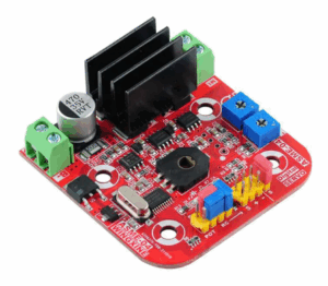
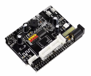
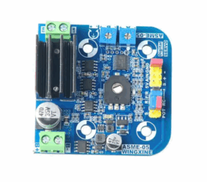
Identifying components (e.g., gate drivers, microcontrollers, encoders, motor interfaces)
-
-
Gerber File and Netlist Recreation
-
Using high-resolution scanners or X-ray imaging to extract inner layers
-
Generating Gerber files, schematic diagrams, and a netlist from the observed copper traces and via interconnections
-
-
Component Functionality Mapping
-
Matching parts to their roles (PWM control, feedback loop, signal conditioning)
-
Building an accurate BOM list through part code recovery and datasheet analysis
-
-
Power and Signal Analysis
-
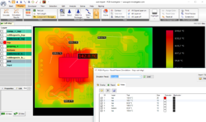
Measuring voltage/current ratings, PWM characteristics, and noise filtering
-
Understanding isolation zones between high-voltage motor drivers and low-voltage logic circuits
-
O objetivo da Análise Eletrônica de Engenharia Reversa de PCB vai além da simples cópia de uma placa física. Requer um conhecimento profundo das características elétricas, da funcionalidade e da interação da placa com o sistema robótico geral. Ao realizar a engenharia reversa de uma placa de circuito impresso (PCB) de controle de servo de braço robótico industrial, nosso processo normalmente inclui:
Inspeção Visual e Estrutural
Avaliação do número de camadas (geralmente de 4 a 8 em PCBs de servo)
Identificação de componentes (por exemplo, controladores de porta, microcontroladores, encoders, interfaces de motor)
Recriação de Arquivo Gerber e Netlist
Uso de scanners de alta resolução ou imagens de raio-X para extrair camadas internas
Geração de arquivos Gerber, diagramas esquemáticos e uma netlist a partir dos traços de cobre observados e por meio de interconexões
Mapeamento da Funcionalidade dos Componentes
Correspondência das peças com suas funções (controle PWM, malha de feedback, condicionamento de sinal)
Construção de uma lista de materiais (BOM) precisa por meio da recuperação do código da peça e análise de folha de dados
Análise de Potência e Sinal
Medição de classificações de tensão/corrente, características PWM e filtragem de ruído
Compreensão das zonas de isolamento entre controladores de motor de alta tensão e circuitos lógicos de baixa tensão
Dificuldades Enfrentadas Durante a Engenharia Reversa
Placas de controle de servo em braços robóticos são altamente otimizados para confiabilidade, precisão e resistência a EMI. Isso torna a engenharia reversa particularmente desafiadora:
Firmware e Microcontroladores Proprietários
Muitas placas contêm microcontroladores ou FPGAs com código protegido ou criptografado, dificultando a replicação completa da lógica de controle sem desenvolvimento personalizado ou engenharia reversa de firmware.
Roteamento de Sinal de Alta Velocidade
Caminhos de temporização críticos e sinais PWM de alta frequência exigem controle preciso da impedância do traço. Qualquer interpretação errônea no desenho do layout pode levar à instabilidade ou jitter do motor.
Domínios de Potência Isolados
Placas servo frequentemente usam optoisoladores e planos de aterramento separados para sistemas de controle de motores e lógicos. A identificação incorreta desses limites de isolamento durante o processo reverso pode causar falhas catastróficas.
Empilhamento de PCB Híbrido
The PCB Reverse Engineering Electronic Analysis defines the input/output parameters of PCB, also refers to the voltage, currency and power, it is necessary to define input terminal pin number and then figure out the output voltage, if there is any display to show the content of the device engineer need to lit up the device in advance to record it, component characteristics include the capacitor and resistor’s value, tolerance and footprint, as well as other parts such as inductor, oscillators and integrated circuits, circuit paths on the gerber file, layout diagram and schematic, material include the metal parts and printed circuit board raw material, crating and bonding necessary to reproduce the candidate through PCB reverse engineering.
The documentation available on the candidate may range anywhere from complete to non-existent.
PCB Reverse Engineering Electronic Analysis Objective
Validate documentation
Design parameters will be used for subsequent PCB layout and functionality modification;
Prescribed test procedures include the electronic/electrical test for its functionality;
PCB 역엔지니어링 전자 분석 목표는 단순히 물리적인 보드를 복사하는 데 그치지 않습니다. 보드의 전기적 특성, 기능, 그리고 전체 로봇 시스템과의 상호작용에 대한 심층적인 이해가 필요합니다. 산업용 로봇 팔 서보 제어 PCB를 리버스 엔지니어링할 때, 일반적으로 다음 프로세스가 포함됩니다.
시각적 및 구조적 검사
레이어 수 평가(서보 PCB의 경우 일반적으로 4~8개)
구성 요소 식별(예: 게이트 드라이버, 마이크로컨트롤러, 인코더, 모터 인터페이스)
거버 파일 및 넷리스트 재생성
고해상도 스캐너 또는 X선 이미징을 사용하여 내부 레이어 추출
관찰된 구리 트레이스 및 비아 상호 연결에서 거버 파일, 회로도 및 넷리스트 생성
구성 요소 기능 매핑
부품을 해당 역할(PWM 제어, 피드백 루프, 신호 컨디셔닝)에 맞게 매칭
부품 코드 복구 및 데이터시트 분석을 통한 정확한 BOM 목록 작성
전력 및 신호 분석
전압/전류 정격, PWM 특성 및 노이즈 필터링 측정
고전압 모터 드라이버와 저전압 논리 회로 간의 절연 영역 이해
리버스 엔지니어링 중 발생하는 어려움
로봇 팔의 서보 제어 보드는 신뢰성, 정밀성 및 EMI 내성을 위해 고도로 최적화되어 있습니다. 이러한 점 때문에 리버스 엔지니어링은 특히 어렵습니다.
독점 펌웨어 및 마이크로컨트롤러
많은 보드에는 보호되거나 암호화된 코드가 포함된 마이크로컨트롤러 또는 FPGA가 포함되어 있어, 맞춤형 개발이나 리버스 펌웨어 엔지니어링 없이는 제어 로직을 완벽하게 복제하기 어렵습니다.
고속 신호 라우팅
중요한 타이밍 경로와 고주파 PWM 신호는 정밀한 트레이스 임피던스 제어를 필요로 합니다. 레이아웃 도면을 잘못 해석하면 불안정성이나 모터 지터가 발생할 수 있습니다.
절연형 전원 도메인
서보 보드는 모터 제어 및 로직 시스템에 광절연기와 별도의 접지면을 사용하는 경우가 많습니다. 리버스 프로세스 중에 이러한 절연 경계를 잘못 식별하면 심각한 고장이 발생할 수 있습니다.
하이브리드 PCB 스택업
Configuration and dimensional tolerance data;
Producibility or a like item at reduced cost not using unrestricted or proprietary information, and QC/QA (quality assurance) information.
Servo control boards in robotic arms are highly optimized for reliability, precision, and EMI resistance. This makes reverse engineering particularly challenging:
-
Proprietary Firmware and Microcontrollers
Many boards contain microcontrollers or FPGAs with protected or encrypted code, making it difficult to fully replicate the control logic without custom development or reverse firmware engineering. -
High-Speed Signal Routing
Critical timing paths and high-frequency PWM signals require precise trace impedance control. Any misinterpretation in the layout drawing may lead to instability or motor jitter. -
Isolated Power Domains
Servo boards often use opto-isolators and separate ground planes for motor control and logic systems. Misidentifying these isolation boundaries during the reverse process can cause catastrophic failures. -
Hybrid PCB Stack-Ups
With thick copper areas and multilayer routing, reconstructing accurate cad files from a prototype or damaged board requires advanced tools and experience.
Once the PCB reproduction is completed, manufacturing requires strict adherence to:
-
IPC class 2 or 3 standards
-
Controlled impedance design
-
Selective soldering or wave soldering for heavy components
-
Use of thermal reliefs and heat sinks for power stages
Boards are then tested under simulated load to verify that all signals and current-handling paths behave identically to the original system.
Through our expert PCB reverse engineering process, we help clients recover, remanufacture, or even improve complex servo control PCBs for industrial robots. Our goal is not just to clone a board—but to thoroughly analyze its electronic parameters, system function, and physical layout to ensure long-term performance and compatibility.
PCB Tersine Mühendislik Elektronik Analiz Hedefi, fiziksel bir kartı kopyalamanın ötesine geçer. Kartın elektriksel özellikleri, işlevselliği ve genel robotik sistemle etkileşimi hakkında derinlemesine bir anlayış gerektirir. Endüstriyel bir robot kolu servo kontrol PCB’sinin tersine mühendisliğini yaparken, sürecimiz genellikle şunları içerir:
Görsel ve Yapısal İnceleme
Katman sayısını değerlendirme (genellikle servo PCB’lerde 4-8)
Bileşenleri tanımlama (örneğin, kapı sürücüleri, mikrodenetleyiciler, kodlayıcılar, motor arayüzleri)
Gerber Dosyası ve Netlist Yeniden Oluşturma
İç katmanları çıkarmak için yüksek çözünürlüklü tarayıcılar veya X-ışını görüntüleme kullanma
Gözlemlenen bakır izlerinden ve ara bağlantılar aracılığıyla Gerber dosyaları, şematik diyagramlar ve bir netlist oluşturma
Bileşen İşlevselliği Eşlemesi
Parçaları rollerine eşleştirme (PWM kontrolü, geri besleme döngüsü, sinyal koşullandırma)
Parça kodu kurtarma ve veri sayfası analizi yoluyla doğru bir BOM listesi oluşturma
Güç ve Sinyal Analizi
Gerilim/akım derecelendirmelerini, PWM özelliklerini ve gürültü filtrelemeyi ölçme
Yüksek voltajlı motor sürücüleri ile düşük voltajlı mantık devreleri arasındaki izolasyon bölgelerini anlama
Tersine Mühendislik Sırasında Karşılaşılan Zorluklar
Servo kontrol panoları robotik kollar güvenilirlik, hassasiyet ve EMI direnci için oldukça optimize edilmiştir. Bu, tersine mühendisliği özellikle zorlu hale getirir:
Özel Ürün Yazılımı ve Mikrodenetleyiciler
Birçok kart, korumalı veya şifreli koda sahip mikrodenetleyiciler veya FPGA’lar içerir ve bu da özel geliştirme veya ters ürün yazılımı mühendisliği olmadan kontrol mantığını tam olarak kopyalamayı zorlaştırır.
Yüksek Hızlı Sinyal Yönlendirme
Kritik zamanlama yolları ve yüksek frekanslı PWM sinyalleri hassas iz empedans kontrolü gerektirir. Düzen çizimindeki herhangi bir yanlış yorumlama, dengesizliğe veya motor titremesine yol açabilir.
Yalıtılmış Güç Alanları
Servo kartları genellikle motor kontrolü ve mantık sistemleri için opto-izolatörler ve ayrı toprak düzlemleri kullanır. Ters işlem sırasında bu izolasyon sınırlarını yanlış belirlemek, felaketle sonuçlanan arızalara neden olabilir.
Hibrit PCB Yığını


