A Circuit Attack Counter PCB is a specialized printed circuit board designed to protect sensitive electronics—particularly microcontrollers, memory chips, and secure logic circuits—from various forms of physical and side-channel attacks. These attacks may include glitching, fault injection, power analysis, timing attacks, electromagnetic (EM) analysis, or even invasive tampering. The purpose of the Circuit Attack Counter PCB is to detect, log, and/or actively counteract attempts to interfere with or extract secure data from the system.

Cómo aplicar ingeniería inversa a una PCB antiataques de circuitos La ingeniería inversa de una PCB tan crítica para la seguridad es muy compleja y suele realizarse con fines de investigación o pruebas de penetración. Así es como los profesionales pueden abordarlo: 1. Inspección visual e imágenes Utilice escaneo óptico de alta resolución o imágenes de rayos X para visualizar el apilamiento de capas Identifique estructuras, mallas de tierra y enrutamiento inusual diseñado para la detección de manipulaciones Busque mallas metálicas o trazas de sensores incrustadas en las capas superiores de la PCB 2. Eliminación destructiva de capas Lije cuidadosamente o elimine químicamente las capas para recrear los archivos Gerber Tome fotos en cada paso para reconstruir el plano de diseño y la lista de conexiones Identifique y catalogue los componentes para una lista de materiales
These PCBs are typically found in applications such as:
-
Cryptographic devices (e.g., smartcards, secure authentication modules)
-
Secure microcontrollers in military and aerospace electronics
-
Tamper-proof payment terminals or point-of-sale devices
-
Digital rights management (DRM) modules
-
IoT devices requiring embedded security
Key Features of a Circuit Attack Counter PCB:
-
Sensors for Attack Detection:
-
Light sensors to detect physical tampering (e.g., enclosure opening)
-
Temperature and voltage monitoring circuits
-
Current sensing to detect abnormal draw (e.g., glitching)
-
-
Power Line Filtering & Regulation:
-
Specialized power filters to block injected noise or voltage spikes
-
Detection circuits for voltage fault injection (VFI) attempts
-
-
Shielding and Redundancy:
-
Metallic shielding layers within the PCB
-
Redundant traces to confuse X-ray imaging or layer-by-layer delayering
-
Meshes that trigger a self-destruct response if broken
-
-
Countermeasures:
-
Reset, disable, or zeroize memory contents upon tampering detection
-
Timing noise injection to resist power or timing analysis
-
Randomized clock generation to prevent synchronization with attack waveforms
-
Reverse engineering such a security-critical PCB is very challenging and typically done for research or penetration testing purposes. Here’s how professionals may approach it:
Inżynieria wsteczna tak krytycznej pod względem bezpieczeństwa PCB jest bardzo trudna i zazwyczaj wykonywana w celach badawczych lub w celu przeprowadzenia testów penetracyjnych. Oto, jak mogą do tego podejść profesjonaliści: 1. Wizualna inspekcja i obrazowanie Użyj skanowania optycznego o wysokiej rozdzielczości lub obrazowania rentgenowskiego, aby zobaczyć ułożenie warstw Identyfikuj struktury przelotowe, siatki uziemiające i nietypowe trasy zaprojektowane do wykrywania manipulacji Szukaj metalowej siatki lub śladów czujników osadzonych w górnych warstwach PCB 2. Niszczące usuwanie warstw Ostrożnie zeszlifuj lub usuń chemicznie warstwy, aby odtworzyć pliki Gerber
1. Visual Inspection & Imaging
-
Use high-resolution optical scanning or X-ray imaging to view layer stack-up
-
Identify via structures, ground meshes, and unusual routing designed for tamper detection
-
Look for metal mesh or sensor traces embedded in upper PCB layers
2. Destructive Layer Removal
-
Carefully sand down or chemically remove layers to recreate Gerber files
-
Take photos at each step to rebuild the layout drawing and netlist
-
Identify and catalog components for a BOM list
3. Signal Tracing
-
Use oscilloscope and logic analyzers to probe test points
-
Capture clock lines, power rails, sensor inputs, and interrupt triggers
-
Identify if the system uses active countermeasures (e.g., resets on probe contact)
4. Firmware & Code Extraction
-
If ICs are readable, dump firmware for static analysis
-
Use fault injection methods (like voltage glitching) if protected by lock bits
1. Визуальный осмотр и визуализация Используйте оптическое сканирование высокого разрешения или рентгеновское сканирование для просмотра слоев Определите с помощью структур, сеток заземления и необычной маршрутизации, предназначенных для обнаружения несанкционированного доступа Ищите металлические сетки или следы датчиков, встроенные в верхние слои печатной платы 2. Разрушающее удаление слоев Тщательно отшлифуйте или химически удалите слои, чтобы воссоздать файлы Gerber Делайте фотографии на каждом этапе, чтобы восстановить чертеж компоновки и список соединений Определите и каталогизируйте компоненты для списка BOM 3. Трассировка сигналов Используйте осциллограф и логические анализаторы для проверки контрольных точек Захватите линии синхронизации, шины питания, входы датчиков и триггеры прерываний Определите, использует ли система активные контрмеры (например, сброс при контакте зонда)
5. Netlist & Schematic Recovery
-
From captured data, reconstruct a schematic diagram
-
Translate into a CAD file for analysis or remodification
Since low power circuits tend to use high value resistors to conserve power, this tends to make the High Circuit Impedance on Circuit Attack Counter PCB Reverse Engineering more susceptible to externally induced radiated noise and conducted noise. Even a small amount of parasitic capacitance can create a significant conduction path for noise to penetrate.
For example, as little as 1 pF of parasitic capacitance allows a 5 V logic transition to cause a large disturbance in a 100 kΩ circuit as illustrated in below Figure:
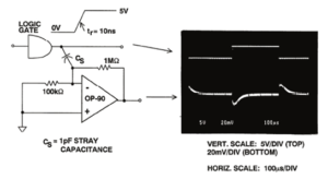
High Circuit Impedances Increase Susceptibility to Noise Pickup
This serves to illustrate that high impedance circuits are full of potential parasitics which can cause a good paper design to perform poorly when actually implemented. One needs to pay particular attention to the routing of signals. Interestingly, many high frequency layout techniques for eliminating parasitics can also be applied here for low frequency, low power circuits—for different reasons.
As discussed in the chapter on amplifiers, current feedback amplifiers do not like to have capacitances on their inputs. To that end, ground planes should be cut back from the input pins as shown in below Figure, which is an evaluation board for the AD8001 high speed current feedback amplifier. The effect of even small capacitance on the input of a current feedback amplifier is shown in below Figure. Note the ringing on the output.
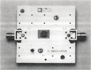
AD8001AR (SOIC) Evaluation Board


