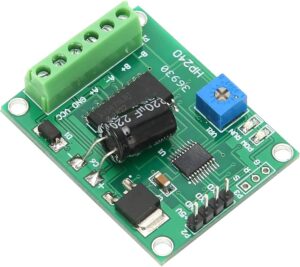
Motor driver PCBs in industrial robotic arms are not standalone circuit boards. They are intricately embedded in electromechanical systems and are mechanically coupled with power transistors, heatsinks, connectors, and mounting brackets. Every hole, edge clearance, and connector alignment must match precisely with the host robot structure.
During PC board reverse engineering, we begin by capturing the exact mechanical layout of the original board. This includes:
-
PCB outer dimensions and contours
-
Mounting hole positions and diameters
-
Connector locations and heights
-
Component heights and heat dissipation zones
-
Heatsink-to-component clearance and screw thread types
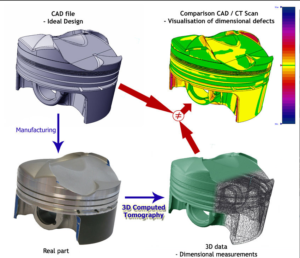
Our process utilizes high-precision 3D scanners, calipers, and CMM (Coordinate Measuring Machine) tools to extract physical measurements. We then integrate these measurements into CAD files for accurate board modeling and fixture compatibility.
In many cases, manufacturing methods, such as punched parts, injection molded, or investment cast parts, indicate Mechanical Parts Dimensional Analysis in PC Board Reverse Engineering.

Nel processo di reverse engineering di schede a circuito stampato, in particolare per sistemi altamente specializzati come i driver per motori di bracci robotici industriali, la precisione dimensionale è un fattore critico. Il nostro servizio di reverse engineering offre un supporto completo non solo nella riproduzione di schede a circuito stampato, file Gerber, schemi elettrici e distinte base, ma anche nell’esecuzione di analisi dimensionali dettagliate dei componenti meccanici per garantire la clonazione, la replicazione o la rigenerazione di questi complessi assemblaggi di PCB.
(1) Normally, items that are sheared or punched do not require a good surface finish on the sheared edge. However, in some cases, the manufacturer will intentionally punch a hole with a minimum clearance between the punch and the die. This is done to create a larger “straight land” in the hole, which may be required as a load bearing surface or to minimize wear on mating parts. When reverse engineering a punched hole, the “land-width” should be noted. If it is more than 25% of the length of the hole, it could be intentional.

Mechanical Parts Dimensional Analysis in PC Board Reverse Engineering
(2) In addition to the draft and parting lines, ejection-pin locations should be included in the final drawing.
Joining methods such as riveting or spot-welding may require testing to determine the strength requirements. Many spot-welded items are controlled at the weld by pull-tests. If necessary, applicable specifications should be reviewed for inclusion in the final TDP.
Heat treatment should be evaluated, using cross sections as required to determine case depth, grain structure and other metallurgical requirements. Grain flow on forgings should be noted.
Whenever a pressed-in bushing exists, concentricity of that bushing to the diameter securing it should be ensured.
If dowel pins are used to align mating parts, the location of the pins at the projected distance should be ensured to assure the fit of those parts.
Once the dimensional analysis is complete, we proceed with circuit-level reverse engineering. The motor driver PCB typically includes:
-
IGBT or MOSFET switching circuits
-
PWM control logic, driven by microcontrollers or DSPs
-
Gate drivers with isolation circuits
-
Feedback loops for current, voltage, and thermal sensing
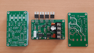
These components work together to drive motors with precision, and any mistake in replication can result in performance loss or hardware failure. We extract the netlist, trace routing, and layer stack to rebuild the layout drawing and Gerber data with full accuracy.

No processo de Engenharia Reversa de Placas de Circuito Único (PCBs), especialmente para sistemas altamente especializados, como PCBs de acionamento de motores de braços de robôs industriais, a precisão dimensional é um fator crítico. Nosso serviço de engenharia reversa oferece suporte abrangente não apenas na reprodução da placa de circuito eletrônico, arquivos Gerber, diagramas esquemáticos e listas de BOM, mas também na realização de análises dimensionais detalhadas de peças mecânicas para garantir a clonagem, replicação ou remanufatura bem-sucedidas desses conjuntos complexos de PCBs.
Surface finishes on all mating surfaces should be checked, whether or not a gasket is used. Casting surfaces subject to wear for grain structure variances caused by special casting processes should be examined using chills to “harden” the casting in that particular area. Electrical wire diameters should be measured and insulation type and thickness noted. The length of the wire should be duplicated even if it appears to be excessive. Shortening a wire length could change the electrical characteristics of the end item.
Cloning a robot arm motor driver PCB is not a simple duplication task. Several challenges often arise:
-
Multilayer PCB stack-ups (often 6–12 layers) require layer-by-layer analysis, sometimes destructively
-
Proprietary components with unknown part numbers complicate BOM list recovery
-
High-current traces require exact replication of copper weight and thermal reliefs
-
Precise connector matching with the robot’s harness is vital—any misalignment may cause system malfunction
-
Firmware embedded in controllers may be encrypted or locked, complicating full system recovery
We address these difficulties with a combination of manual trace inspection, digital image processing, and specialized de-soldering and scanning techniques to ensure a faithful reproduction of both the electronic and mechanical systems.
Manufacturing Considerations
Once the board is successfully reverse engineered, we guide or manage the remanufacturing process. This includes:
-
Generating updated Gerber files and schematic diagrams
-
Producing prototypes for functional and mechanical testing
-
Selecting high-quality PCB substrates with adequate thermal and mechanical properties
-
Verifying the assembly against original form-fit-function (FFF) requirements
Conclusion

En el proceso de ingeniería inversa de placas de circuito impreso (PCB), especialmente en sistemas altamente especializados como las PCB de controladores de motores de brazos robóticos industriales, la precisión dimensional es un factor crucial. Nuestro servicio de ingeniería inversa ofrece soporte integral no solo para la reproducción de la placa de circuito electrónico, archivos Gerber, diagramas esquemáticos y listas de materiales (BOM), sino también para el análisis dimensional detallado de las piezas mecánicas para garantizar la clonación, replicación o remanufactura exitosa de estos complejos conjuntos de PCB.
Through our PC Board Reverse Engineering service, we deliver not just a copied circuit, but a fully integrated and dimensionally accurate motor driver PCB ready for deployment in industrial robotic arms. Our emphasis on mechanical parts dimensional analysis ensures that the cloned boards meet stringent industry demands for performance, reliability, and compatibility. Whether your goal is to restore an obsolete design, duplicate a legacy module, or reproduce a mission-critical control unit, we offer the precision and expertise necessary to bring your hardware back to life.


