In the field of advanced automation, the industrial robot main control PCB stands as a critical hub for coordinating movement, logic, communication, and feedback control. This multilayer printed circuit board serves as the core of the robot’s “brain,” managing real-time tasks with high precision and reliability. When the original design files are unavailable—due to discontinued models, vendor lock-in, or obsolete components—industrial robot main control PCB reverse engineering becomes a valuable strategy to restore or duplicate the original functionality.
Unique Features of Main Control PCBs in Industrial Robots
Unlike general-purpose PCBs, the main controller board in an industrial robot must meet demanding technical requirements:
-
Multilayer complexity: Often 6 to 12 layers or more, integrating logic, power, analog feedback, and high-speed communication signals.
-
High-speed signal routing: For motion algorithms and servo loop updates in real time.
-
Embedded processors or FPGAs: For executing control logic, safety protocols, and feedback processing.
-
Mixed-signal architecture: Combining analog sensor inputs with digital processing.
-
Industrial-grade durability: Heat resistance, shock tolerance, and long-term reliability in harsh environments.
These PCBs must also support communication interfaces like CAN bus, EtherCAT, RS-485, or Profinet, making their layout and signal integrity design even more critical.
Challenges in Reverse Engineering the Main Control PCB
The process of reverse engineering, cloning, or reproducing such a complex board involves multiple technical obstacles:
-
Multilayer Gerber File Reconstruction
Capturing the internal layer structure, including power planes and signal routing, requires destructive methods or X-ray imaging. Reconstructing the full Gerber file, schematic diagram, and layout drawing with accuracy is time-intensive. -
Component Identification and BOM Recovery
Many ICs used in robotic systems are custom, masked, or rebranded, complicating the BOM list recreation. Without a clear netlist and part numbers, substitute selection becomes risky and may affect timing, voltage tolerance, or performance. -
Firmware and Logic Analysis
The presence of microcontrollers or programmable logic devices (like FPGAs) often means firmware extraction is necessary. If firmware is encrypted or protected, complete duplication is impossible without code reconstruction or reverse logic modeling. -
Signal Integrity and EMI Compliance
High-speed buses and PWM signals used for motion control require precise PCB layout and impedance matching. Even slight deviations during remanufacture can introduce signal noise, jitter, or malfunction. -
Heat Management and Layer Stackup
Replicating the thermal management strategy (e.g., copper pours, thermal vias) and correct layer stackup is essential. Failure here leads to overheating, reduced lifespan, or degraded system performance.
Manufacturing Considerations
Manufacturing a duplicated industrial robot control PCB after reverse engineering requires:
-
High-Tg FR-4 or specialized substrates for thermal stability
-
Advanced PCB fabrication capable of handling microvias, buried vias, and tight tolerances
-
Automated optical inspection (AOI) and functional testing to validate the replicated board
-
Precise SMT and THT assembly with industrial-grade solder profiles
Close attention must be paid to the cad file and gerber data, ensuring all elements from pads to polygons are consistent with the original.
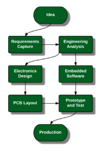
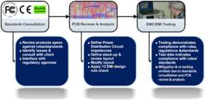
Printed Circuit Board Reverse Engineering Test includes three phases from initial inspection, test plan objective to worse-case analysis:
First consideration is Initial inspection
The test requirements to be determined include initial inspection and testing of the hardware provided for printed circuit board reversing engineering, and for inspection and acceptance of the prototype to be built and tested in accordance with the preliminary Technical Drawing Package. Special testing and test equipment/fixture requirements should be identified and a test plan developed.
Test plan objective
The objective of the test plan is to verify adherence to the requirements delineated in the applicable specifications and standards, including verification of performance, determination of reliability and endurance, and verification of structural integrity.
Worse-case analysis
If the available documentation lacks sufficient test data, a worse-case analysis should be performed to develop testing criteria and procedures, including critical failure modes and limitations. Experts in the field should be contacted to identify common failure areas. The tests for item failure limits, such as overload, fatigue, vibration, and temperature, are the most convincing means of ensuring equivalence of manufacture.
The Acceptance Test Procedures should define these requirements and specify the test procedures in accordance with the applicable specifications and standards. A Printed circuit board sample Test Plan Format is provided in below figure.


