In the realm of modern industrial electronics, power module circuit cards play a pivotal role in managing and distributing electrical energy with precision and stability. These printed circuit boards (PCBs) are engineered to withstand high current loads, manage thermal stress, and ensure consistent power delivery across complex systems. Whether integrated into industrial motor drives, renewable energy inverters, automotive power systems, or heavy-duty robotics, these boards serve as the electrical backbone. The process of power module circuit card cloning—whether for repair, redesign, or reverse engineering—presents a unique set of challenges due to the complexity and durability requirements of these systems.

O processo de clonagem, replicação ou engenharia reversa de uma placa de módulo de potência requer não apenas habilidade técnica, mas também um profundo conhecimento de eletrônica de potência e princípios de projeto de PCB. Algumas das principais dificuldades incluem:
Construção Multicamadas e Extração de Arquivos Gerber
Placas de módulos de potência geralmente contêm de 4 a 12 camadas, tornando a recriação de arquivos Gerber a partir de uma amostra física extremamente difícil. As camadas internas devem ser analisadas por métodos destrutivos ou varredura de raios X de alta resolução para reconstruir a netlist, o arquivo CAD e o desenho do layout.
Identificação de Componentes e Recuperação de Lista de Materiais (BOM)
Muitos componentes de alta potência são proprietários ou personalizados, e as etiquetas serigrafadas padrão podem ser removidas ou ocultadas. A recuperação precisa da lista de BOM torna-se desafiadora, especialmente ao tentar obter peças obsoletas ou de nível militar.
Projeto de Gerenciamento Térmico
O processo de clonagem deve levar em conta as restrições do projeto térmico, incluindo o posicionamento das vias térmicas, vazamentos de cobre e integração do dissipador de calor. Uma replicação inadequada pode levar à fuga térmica ou falha do sistema.
Unique Features of Power Module PCBs
Power module PCBs are not typical electronic boards. They feature:
-
Thick copper layers (often 2oz to 6oz) to handle high current flow
-
High-voltage insulation and isolation zones between control and power sections
-
Integrated thermal management, such as heat sinks or thermal vias for effective heat dissipation
-
Mixed-signal integration, combining analog monitoring circuits and digital control units
-
High-reliability components like IGBTs, MOSFETs, and gate driver ICs
These circuit cards are often part of multi-board systems, tightly coupled with sensors, logic controllers, and communication interfaces, all working in harsh industrial environments with fluctuating temperatures and electromagnetic interference.
Challenges in Cloning Power Module Circuit Cards
The process of cloning, replicating, or reverse engineering a power module board requires not only technical skill but also a deep understanding of power electronics and PCB design principles. Some of the key difficulties include:
-
Multi-Layer Construction & Gerber File Extraction
Power module boards often contain 4 to 12 layers, making Gerber file recreation from a physical sample extremely difficult. Internal layers must be analyzed through destructive methods or high-resolution X-ray scanning to reconstruct the netlist, cad file, and layout drawing. -
Component Identification & BOM Recovery
Many high-power components are proprietary or custom-packaged, and standard silkscreen labels may be removed or obscured. Accurate BOM list recovery becomes challenging, especially when trying to source obsolete or military-grade parts. -
Thermal Management Design
The cloning process must account for thermal design constraints, including the placement of thermal vias, copper pours, and heat sink integration. Poor replication can lead to thermal runaway or system failure. -
High Voltage Isolation
Ensuring proper creepage and clearance distances is vital. Even slight errors in PCB reproduction can compromise insulation, leading to catastrophic failure in high-voltage environments. -
Firmware & Control Logic
Many power module PCBs include embedded microcontrollers or FPGAs for PWM control, feedback regulation, and system protection. Without access to the original firmware, reverse engineering the logic behavior is exceptionally challenging.

Proces klonowania, replikacji lub inżynierii wstecznej płytki modułu zasilania wymaga nie tylko umiejętności technicznych, ale także głębokiego zrozumienia elektroniki mocy i zasad projektowania PCB. Niektóre z głównych trudności obejmują: Konstrukcja wielowarstwowa i ekstrakcja pliku Gerber Płytki modułów zasilania często zawierają od 4 do 12 warstw, co sprawia, że odtworzenie pliku Gerber z fizycznej próbki jest niezwykle trudne. Warstwy wewnętrzne muszą zostać przeanalizowane za pomocą metod destrukcyjnych lub skanowania rentgenowskiego o wysokiej rozdzielczości, aby zrekonstruować listę połączeń, plik CAD i rysunek układu. Identyfikacja komponentów i odzyskiwanie BOM Wiele komponentów dużej mocy jest zastrzeżonych lub pakowanych na zamówienie, a standardowe etykiety sitodrukowe mogą zostać usunięte lub zasłonięte. Dokładne odzyskiwanie listy BOM staje się trudne, szczególnie w przypadku próby pozyskania przestarzałych lub wojskowych części.
Manufacturing Considerations
Once cloning is successful, remanufacturing such boards requires advanced fabrication capabilities:
-
Thick copper plating and precision etching to maintain current-carrying capacity
-
High-temperature PCB substrates like FR-4 High-Tg or metal-core boards
-
Selective soldering or reflow processes suitable for heavy components
-
Rigorous testing, including high-voltage stress testing and thermal cycling
These manufacturing requirements must be aligned with the original design to ensure functional equivalence and long-term reliability.
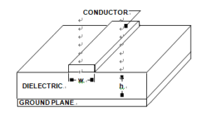
The benefits of outward and return signal paths being close together so that inductance is minimized. As shown previously in Figure 7-30, when an HF signal flows in a PC track running over a ground plane, the arrangement functions as a microstrip transmission line in Power Module Circuit Card Cloning, and the majority of the return current flows in the ground plane directly underneath the line.
Below Figure shows the general parameters for a microstrip transmission line, given the conductor width, w, dielectric thickness, h, and the dielectric constant, Er.

A PCB Microstrip Transmission Line Is an Example of a Controlled Impedance Conductor Pair
The characteristic impedance of such a microstrip line will depend upon the width of the track and the thickness and dielectric constant of the PCB material. Designs of microstrip lines are covered in more detail later in this chapter.
For most dc and lower frequency applications, the characteristic impedance of PCB traces will be relatively unimportant. Even at frequencies where a track over a ground plane behaves as a transmission line, it is not necessary to worry about its characteristic
impedance or proper termination if the free space wavelengths of the frequencies of interest are greater than ten times the length of the line.
However, at VHF and higher frequencies it is possible to use PCB tracks as microstrip lines within properly terminated transmission systems. Typically the microstrip will be designed to match standard coaxial cable impedances, such as 50, 75, or 100,
simplifying interfacing.
Note that if losses in such systems are to be minimized, the PCB material must be chosen for low/high frequency losses. This usually means the use of Teflon or some other comparably low-loss PCB material. Often, though, the losses in short lines on cheap
glass-fiber board are small enough to be quite acceptable.

Bir güç modülü kartını klonlama, çoğaltma veya tersine mühendislik işlemi yalnızca teknik beceri değil, aynı zamanda güç elektroniği ve PCB tasarım ilkeleri hakkında derin bir anlayış gerektirir. Bazı temel zorluklar şunlardır: Çok Katmanlı Yapı ve Gerber Dosyası Çıkarımı Güç modülü kartları genellikle 4 ila 12 katman içerir ve bu da fiziksel bir örnekten Gerber dosyası yeniden oluşturmayı son derece zorlaştırır. Netlist, cad dosyası ve düzen çizimini yeniden oluşturmak için iç katmanlar yıkıcı yöntemler veya yüksek çözünürlüklü X-ışını taraması yoluyla analiz edilmelidir. Bileşen Tanımlama ve BOM Kurtarma Birçok yüksek güçlü bileşen tescilli veya özel olarak paketlenmiştir ve standart serigrafi etiketleri kaldırılabilir veya gizlenebilir. Özellikle eski veya askeri sınıf parçalar kaynaklamaya çalışırken doğru BOM listesi kurtarma zorlu hale gelir. Termal Yönetim Tasarımı Klonlama işlemi, termal geçişlerin, bakır dökümlerinin ve ısı emici entegrasyonunun yerleştirilmesi dahil olmak üzere termal tasarım kısıtlamalarını hesaba katmalıdır. Kötü çoğaltma, termal kaçak veya sistem arızasına yol açabilir.


